
Tom's Accurate Tools AT300P Review
This webpage was initially created some time ago, so please be sure to read any updates located at the end of the text.
It would appear from their rudimentary single-page website that Accurate Tools is a tiny company located in Birmingham, Michigan (USA). It is likely they simply resell select Chinese-made inverters, welders and a flooring nailer under their own name. I have only seen their products for sale on the large Internet auction site. I discovered that a virtually identical-looking inverter is manufactured by the Fenghua E-Lion Electronics Co., Ltd. of Ningbo, Zhejiang, China and sold as their Model EL-300PA. This is a fairly small manufacturing company, which will also supply OEMs. They sell the inverter for $36 (US) with a minimum order of 300 pieces. I highly suspect they are responsible for the AT300P, even though an Internet search of identifying marks found on the printed circuit boards has led nowhere.
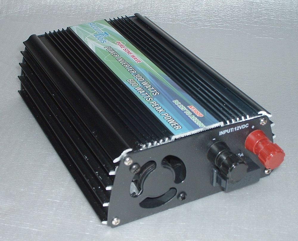
The main body of the Model AT300P inverter is aluminum with stamped steel end pieces that are painted black. The bottom is also stamped steel and may be slid out of its groove once one of the ends has been removed.
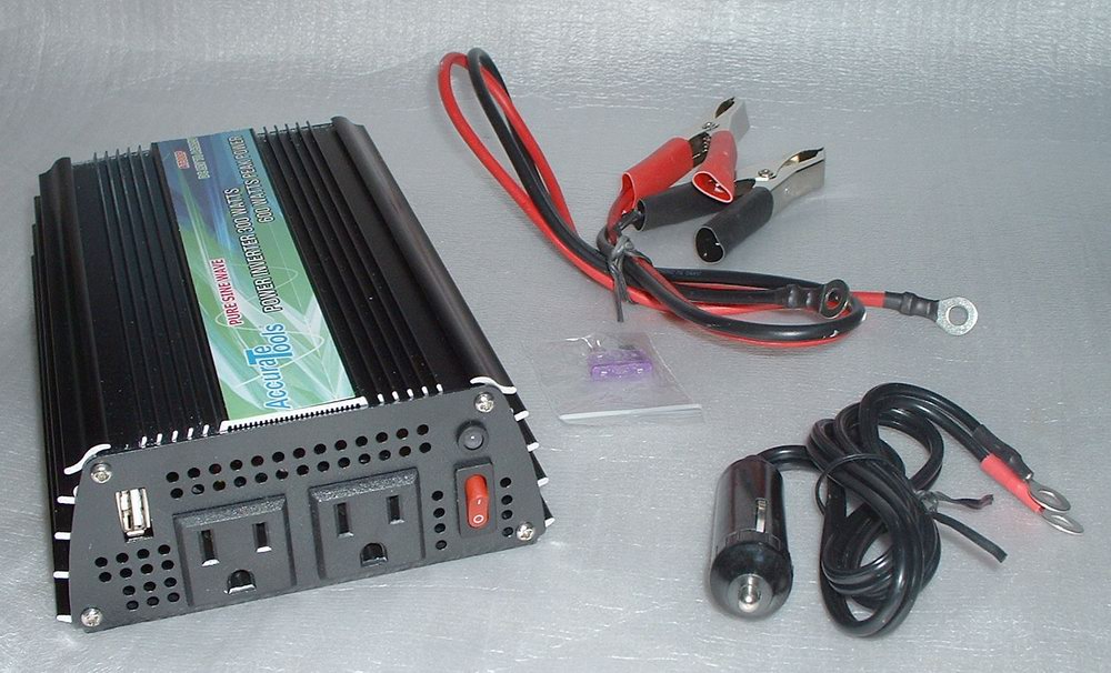
This is an inexpensive inverter as far as the sine wave variety go, sometimes available (shipped) for around $40 if you happen to get lucky. At only 300 Watts (600W peak) it is no powerhouse, but it's more than sufficient for running some CFL lighting and/or sensitive electronic equipment. It is not capable of powering large appliances or most power tools. There are two things about it you should be aware of right off. First, it produces a great deal of RFI (radio frequency interference). This may not be of great concern, unless you like to listen to AM broadcast (MW) or shortwave radio, in which case the buzzing will be intolerable. The second annoyance is that it produces AC at a frequency of 62.5HZ (cycles per second) rather than the normal 60. This would probably only be a problem with timers and clocks that rely on the frequency of the incoming AC power for accuracy, as the power supplies in most equipment likely won't care. The typical electric fan and synchronous motors will run slightly faster than normal, of course. The inverter comes with a set of short interconnecting battery cables (see photo, below), a cable terminated in a lighter plug, and a spare 35A fuse. The full-color instruction manual is of a generic nature and covers 11 different inverters. It does not include a circuit diagram and there is no mention of a warranty.
With some effort, one can work around the two issues mentioned above. I added a plug-in outboard RFI filter between one of the outlets on mine and the electrical wiring it powers. I discovered the interference begins to radiate just as soon as any conductor, however short in length, is inserted into either outlet. Therefore, I made sure to fully shield everything related to the filter I built, which is a surplus unit rated for 5 Amps. I mounted it in an extra-deep rectangular steel electrical box with a metal cover surrounding the standard duplex outlet. I ran the short electrical cord through shielding braid taken from some RG-8/U coaxial cable and attached a metal-clad plug to its end. Between each of the 12-Volt input terminals and the aluminum chassis of the AT300P inverter, I attached an 0.1uF capacitor. I also ran a short length of wire between the chassis and the outside of the metal electrical box containing the RFI filter to connect them together. The grounds on the two AC receptacles on the front of the inverter are not connected to anything, by the way. For the least amount of RFI, I found it best not to connect any of the wiring or the chassis of the inverter to earth ground in my particular situation. The disadvantage of using a filter is that it creates some additional voltage drop due to the resistance of its series inductors. Therefore, it's adviseable to use one designed to carry a fairly high current in order to minimize the loss.
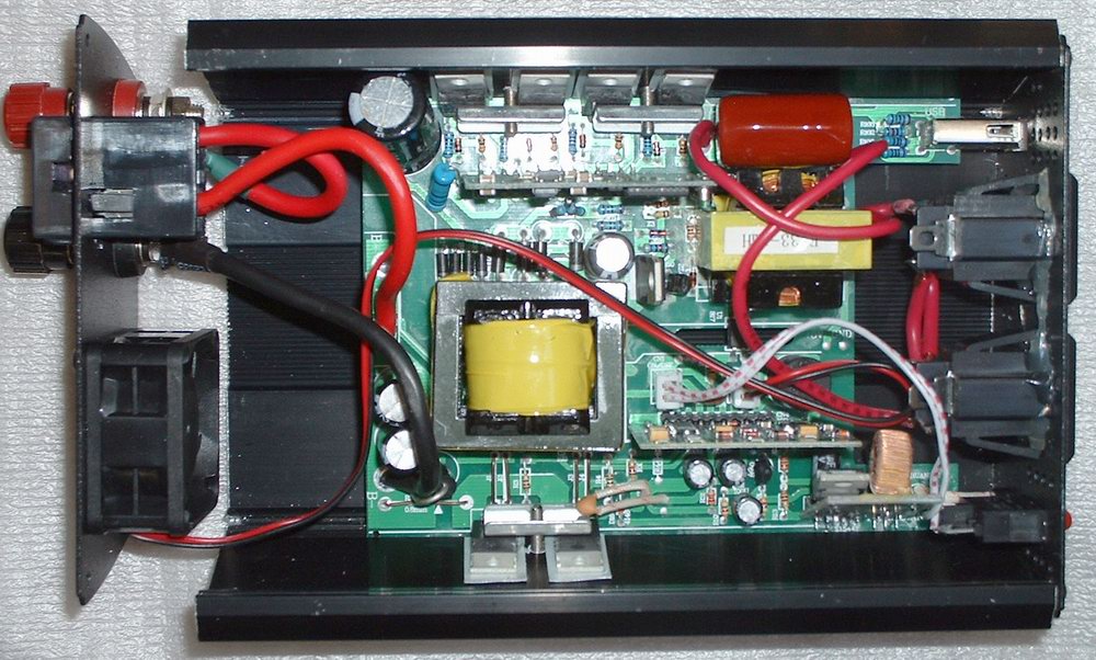
The issue with the frequency being off appears to be the result of the manufacturer's choice of a 20MHz (megacycle) crystal in the oscillator circuit. When divided by 320,000 the 62.5Hz output frequency is obtained. I'm fairly certain this must be the process, as the PC board is silkscreened "16M" beside the crystal, which calculations show would give exactly 50Hz were a 16MHz part to be used in the European version. I was able to locate an Asian source of 19.2MHz crystals in the appropriate HC-49 (short) style and swapped the part in my inverter. A very accurate (within 0.02Hz) and stable 60Hz output resulted and has been maintained through a number of hours of daily use. I can only assume that the choice of a 20MHz crystal was based on its wider availability and thus lower cost than one that would have been more suitable.
For those interested in adding the same frequency-correcting modification to their AT300P inverters, I have a limited number of the crystals available, which I'm willing to sell along with instructions on how to perform the switch (USA addresses only). It does require some careful unsoldering and resoldering with a small tip in tight quarters, so I would only recommend it to an experienced hobbyist. For more information on the offer, please contact me via the information below:
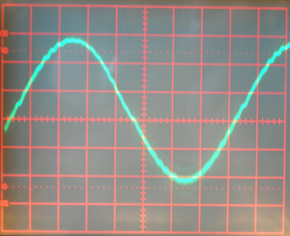
The Accurate Tools AT300P power inverter seems to perform properly otherwise (see update, below). In my tests, the waveform was a sine wave, albeit with some minor raggedness (see photo, below). With 12 Volts applied to the input terminals in an initial test, 119.1VAC RMS (122V on a standard averaging meter) was produced under no-load conditions with an idling current draw of 430mA (0.43A). When running a 13-Watt CFL bulb, the DC current draw was 1.7A, which is similar to that of an inexpensive modified sine wave inverter I own under those same conditions. Connected to a fully-charged battery in a later test, I observed 118.8V (RMS) output under no-load conditions (with 12.7VDC at the terminals), dropping to 113.8V (RMS) (with 11.9VDC at the terminals) while supplying 185 Watts into a resistive load. The ventilation fan comes on above a certain current draw and increases in speed with load. The two power transistors in the low-voltage portion of the circuit are type IRF1404 N-channel MOSFETs. The four power transistors in the high-voltage portion of the circuit are type FTP14N50C N-channel MOSFETs. Both of these semiconductors are rather uncommon. The inverter uses a type LM2576 switching regulator to power the USB jack.
2019 UPDATE: I stopped using my AT300P after several years when it developed a problem with the output voltage fluctuating, which caused an annoying flickering of the lights connected to it. No troubleshooting was done.
| Back to Top |
|---|