
Tom's Casio CTK-720 Keyboard Modification Page
For comparison purposes, I made tape recordings of the keyboard while using the microphone, both before I performed the modification described below, and afterward. A short segment from each is available as a single MP3 file you may listen to by CLICKING HERE. This bit of audio illustrates just how much of an improvement in the fidelity may be expected when using a typical condenser mike with the CTK-720. The microphone and audio hookup were identical in both recordings.
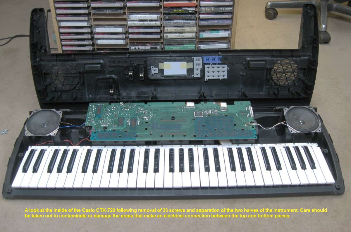
The following information is intended to be used by someone who has at least some experience working on electronic equipment. If that's not you, you'll probably want to find someone else to modify your keyboard for you. To disassemble the instrument, you will need a philips screwdriver with a reasonably long shaft and a fairly small tip. Thirty-three screws must be removed from the bottom in order to gain access to the circuit board inside. Such a large number of fasteners is necessary in order to ensure proper contact between the PC board mounted to the bottom half and the various controls and digital display mounted on the top half of the keyboard. This will become apparent to you once the two halves are separated and you can see inside. Loosen any screw which is not attaching the metal strips underneath the keys. Those should be left alone. The screws are all of the same length, so don't worry about mixing them up. Since it will be almost impossible to fish all of them out of the holes, just unscrew them completely and they'll drop out once the instrument is flipped back over. With the screws loosened, hold the keyboard together and turn it rightside up. You may then remove the top by lifting it up from the front edge, then pushing slightly back to free it from the protruding jacks. If resistance is felt, check to be certain that all 33 of the screws are loose.
Once the upper case has been removed you will see the solder side of the PC board. It is not necessary to remove it, as all work can be done from this side. A word of caution is in order. Because there are a large number of exposed contacts that must not be contaminated, be very careful as you perform your work. Avoid the temptation to blow out any accumulated dust or try to remove it by wiping as this could instead move some of it to an area where it will interfere with getting a good electrical connection when the instrument is reassembled. Better to leave it undisturbed.
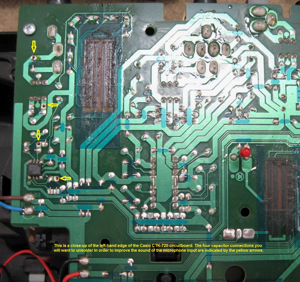
Filtering of the microphone input occurs in three places. First, there is an 0.1uF capacitor soldered directly across the input. This is C120 and, like all the capacitors we are concerned with, is a little green-colored ceramic with axial leads that looks like a resistor. The audio signal then passes through a dual toroidal inductor where it is again filtered by C121. From there it goes through a small electrolytic coupling capacitor to the A and B inputs of an NJM2068D dual low-noise op amp. In addition to feeding the dual microphone level pot, each output of this chip also goes through a feedback loop consisting of an 8.2K Ohm resistor bypassed by a .0056uF capacitor. These capacitors are C105 and C122. This circuit feeds the inverting input of the two opamps, thus reducing the overall gain, but especially on the higher frequencies. The IC is a wideband amplifier, so I suppose it could be argued all this filtering was needed to keep it from oscillating or amplifying well into the megahertz range, but again, the values of the capacitors used in the circuit are excessive for this. Perhaps it was an attempt to reduce the potential for feedback from speakers to microphone, but I haven't encountered any problem with the filtering removed.
Basically, the modification involves electrically removing the four capacitors mentioned above from the circuit. This may be done by unsoldering one end of each of them and pushing the lead down through the board, if desired. I actually chose to leave them in place, after making sure there was a void all the way around between the lead and the pad to which it had been soldered. I used some desoldering wick (braid) to remove the solder, then straightened the bent-over leads of each so they didn't touch the foil. I did not attempt to do a frequency response check or look for furthur filtering as the improvement made by the modifications described was sufficient for my needs.
When reassembling the keyboard, more cautions are in order. First, put the two halves together carefully, back edge first, making sure the red LED power indicator goes through the hole in the top properly. Hold them together while flipping the unit over so you can re-install the screws from the bottom. I suggest only installing every other screw at first until you have verified that the keyboard is working properly, as 33 are a lot to take back out again if there's a problem. Also, there are two places where an internal "catch" is formed from the plastic on the bottom of the keyboard. This leaves a gap through which a screw can fall inside if you're not careful. Based on my own experience, I recommend covering these with a piece of masking tape during reassembly.
Helpful photos are included, below. Good luck!
To contact me, please use the address in the image below.

| Back to Top |
|---|